Automated Cable Routing
for Shipbuilding
Finding a practical solution to a complex engineering problem
The Challenge: Thousands of Cables, Thousands of Routes
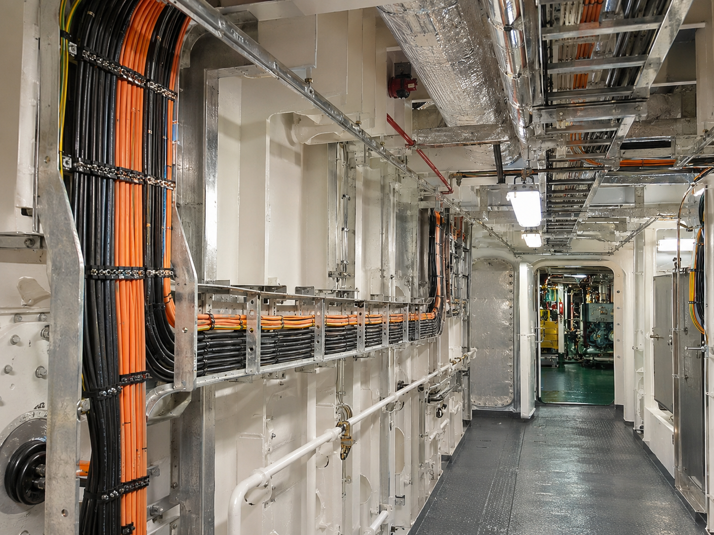
Building a ship or offshore platform involves a complex network of electrical cables connecting equipment across multiple compartments and decks. Some cables travel more than a hundred meters between their starting and ending points.
Before installation, cables must be cut to predetermined lengths and delivered to the vessel. Installation teams need documentation identifying not only where each cable starts and ends, but also the route it must follow.
Accurate planning is essential. Excessively long cables lead to wasted material, unnecessary procurement and storage costs, and additional work during installation. Underestimated lengths can cause shortages and production delays.
Cable trays and penetrations introduce further engineering considerations. Different cable categories may require separation, while cable trays and penetrations have limited physical capacity. The required materials must also be identified and ordered before installation.
Traditionally, cable lengths were often estimated from engineering drawings, previous projects, and practical experience, with additional allowances to compensate for uncertainty.
Across thousands of cables, even relatively small inaccuracies could accumulate into substantial differences between estimated and actual material requirements.
The challenge was to produce sufficiently accurate cable routing information without making the engineering process unnecessarily complicated or time-consuming.
When a Sophisticated Design System Is Not Enough
At Keppel FELS Baltech, our engineering teams used Tribon, an integrated 3D ship design system.
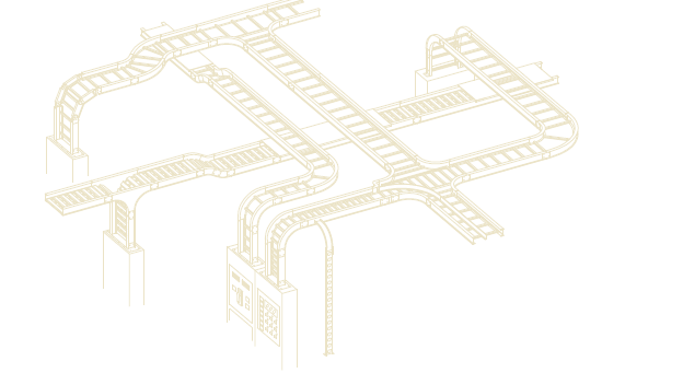
Tribon included specialized electrical design capabilities for modelling cable trays, penetrations, and cables within the vessel's three-dimensional environment. It could calculate cable lengths and generate production documentation.
However, the practical workflow presented difficulties.
A ship or offshore platform may contain tens of thousands of cables. Modelling them in detail required substantial effort, particularly when frequent engineering changes affected cable trays already populated with routed cables.
To accelerate the design process, our engineers adopted a different approach.
Instead of using the dedicated Tribon Cable functionality to model cable trays, they used the Structure Modeling module, which allowed them to create, duplicate, and modify physical structures more efficiently.
The trade-off was that these structures did not form the logical cableway network required for Tribon's automatic cable routing functionality.
As a result, even the available batch-routing capabilities could not be used with our actual modelling workflow.
Engineers compensated by maintaining Excel tables containing selected known cableway distances, estimated lengths, and additional allowances for connections to equipment and cable termination.
This workaround avoided extensive cable modelling but introduced another time-consuming process. Changes required repeated calculations, and conservative estimates accumulated across cable routes.
We had a powerful 3D design system, yet much of the actual cable length calculation remained manual.
Understanding the Work Before Automating It
My background was particularly relevant to this problem.
I began my career designing electrical installations for ships. Later, through Tribon system implementation, administration, and training, I became familiar with both the software and the engineering processes it supported.
When the possibility of automating cable length calculations was raised within the company, there was no predefined technical solution.
I started by examining how the engineers actually worked.
We discussed the information they extracted from the 3D model, their spreadsheet calculations, the required output documents, and the changes they frequently encountered during design.
One principle guided the development:
Automation should reduce engineering effort, not introduce another complicated process that engineers must maintain.
The objective was not to reproduce Tribon's complete 3D cable modelling functionality.
It was to calculate cable routes and lengths efficiently using information the engineers could already obtain with relatively little additional work.
The Breakthrough: From Geometry to Pathfinding
Initially, the problem appeared extremely difficult.
A cable could travel across several decks, change direction repeatedly, and pass through multiple compartments. Finding the shortest available route between two locations seemed to require complex three-dimensional geometric calculations.
I spent considerable time experimenting with possible solutions, drawing networks and routing sequences on paper.
Those attempts were unsuccessful.
Eventually, I looked for existing approaches to automatic pathfinding. Searching specifically for shipboard cable routing algorithms produced little useful information.
Then I considered computer games.
Game engines often need to find routes for characters moving across maps. Perhaps the same mathematical principles could be adapted to cable routing.
I found descriptions of two shortest-path methods for networks of connected points and selected one for experimentation.
After adapting the approach, I built a small two-dimensional test network containing approximately ten to twelve points.
The first attempts required corrections, but eventually the program successfully found the shortest path between two selected points.
I then added route length calculation and support for mandatory intermediate points, allowing engineers to direct cables through selected locations.
The next step was extending the method to three dimensions.
Surprisingly, this was considerably simpler than expected.
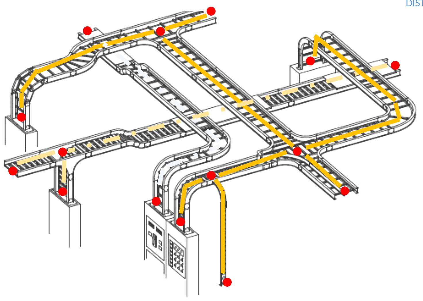
The algorithm did not need to understand the complete three-dimensional geometry of the ship. It only needed to know which points were connected and the measured distance between them.
Once the physical cableway system was represented as a network of connected points, the same pathfinding principles could operate across multiple decks.
The key was finding an appropriate mathematical representation of the engineering problem.
Building the Logical Cableway Network
Cable Routing operated independently of Tribon's cable modelling functionality.
Engineers selected and defined reference points at suitable locations along the existing cableways, based on the actual arrangement of cable trays, penetrations, and routing paths.
These points did not need to correspond to every physical cable tray segment or component. They were placed wherever the engineer considered them necessary to represent the cableway network with sufficient accuracy.
Each reference point was assigned an identifier, and the measured distance along the physical cableway between directly connected points was recorded.
Together, the points and their connections formed a simplified logical network representing the available cable routes.
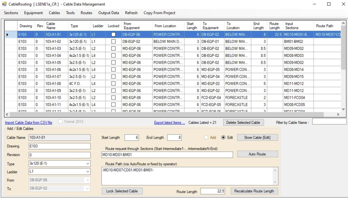
For each cable, the engineers specified the starting and ending locations, any mandatory intermediate points, and the additional lengths required to reach the connected equipment and complete the terminations.
The application then calculated the shortest available route through the defined network, its total length, and the complete sequence of reference points along the path.
This distinction was important: the result was not merely an estimated cable length but an identifiable route that could be included in production documentation.
The accuracy of the results depended on the quality of the input data. A sufficiently detailed network, with correctly measured distances, reduced the remaining lengths that had to be estimated manually.
The engineers could therefore work with a simplified representation of the physical system without losing the information required for practical cable routing.
Making the Software Fit the Engineers
The initial application included a graphical interface for entering and managing engineering data.
However, the engineers preferred using CSV files, allowing them to reuse existing tables and information from previous projects.
I adapted the application accordingly, adding CSV import rather than requiring them to change their established working procedures.
Further improvements followed during practical use.
Input data from different sources sometimes contained inconsistent identifiers, including variations in capitalization. The software needed to accommodate such differences to avoid unnecessary manual corrections.
The engineers also wanted to retain control over routing decisions.
The original application therefore did not automatically enforce cable category or cableway capacity restrictions during path selection. Instead, engineers could specify mandatory intermediate points to guide cables through appropriate parts of the network.
The software performed the calculations while the engineers remained responsible for the routing decisions.
Handling Engineering Changes
One of the most useful capabilities was recalculation after design modifications.
When cableway arrangements changed, engineers could update the relevant reference points or distances and run the routing calculations again.
The application supported recalculation of the complete project or only selected cables.
This avoided manually rebuilding individual cable routes whenever the underlying engineering design changed.
For a process where modifications were normal rather than exceptional, this was a significant practical advantage.
From Calculations to Production Documentation
Cable Routing produced more than cable lengths.
Its output supported engineering, material preparation, and installation activities.
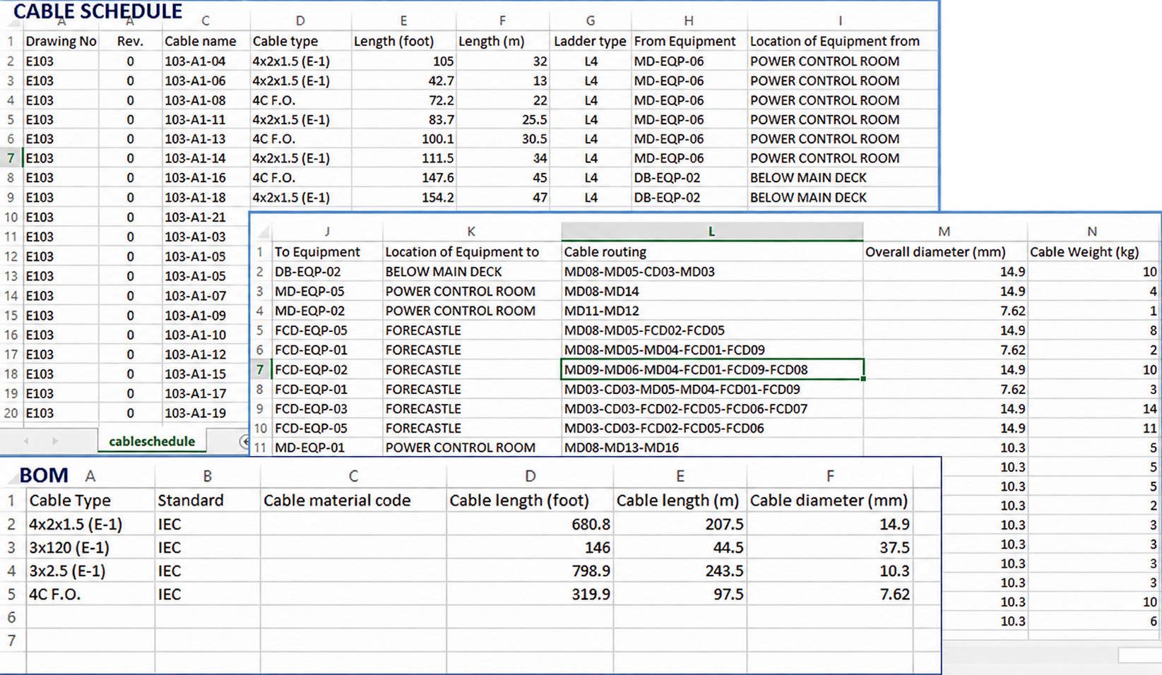
Cable routes and schedules
For each cable, the application calculated its length and retained the complete sequence of reference points along its route.
The results were compiled into cable schedules for use in engineering and production.
Material specifications
The application generated cable Bill of Materials information based on the calculated requirements, supporting procurement and material planning.
Cableway loading information
The software could identify all cables passing through a selected point in the network and calculate their combined cross-sectional area.
Engineers used this information when selecting cable tray dimensions and as an indication of the requirements for cable penetrations.
This was a calculation of the space occupied by cables, not an automatic verification of cableway capacity against engineering rules.
Installation drawings
A particularly practical function generated the list of cables passing through a selected reference point.
The list could be copied to the Windows clipboard and pasted directly into an AutoCAD drawing.
On installation drawings, cable lists placed at selected locations along the cableway system helped workers identify which cables passed through each section and follow the intended routing paths.
The calculated information therefore became part of the actual shipbuilding production documentation.
Verification and Results
Before adopting Cable Routing for ongoing engineering work, the engineers tested it using information from a previously constructed ship project.
They selected an area where the actual cable lengths were already known, prepared the corresponding input data, and compared the program's calculations with the existing project information.
Although the exact numerical differences are no longer available, the results were sufficiently convincing for the team to begin using the application in real projects.
Once the cableway network and cable data were prepared and imported, the application could calculate routes and lengths for an entire project and generate the associated routing information and schedules in approximately 15–20 minutes.
This was the calculation and processing time, not the total time required to prepare the engineering input.
The effect on the workflow was substantial.
Previously, approximately four or five people had been involved in preparing cable routing information. After the application was introduced, the work was handled by one person, while the others were reassigned to different engineering activities.
The application continued to be used in several subsequent projects.
Later, changes in how engineering work was distributed between the company's international offices meant that cable routing activities were no longer regularly assigned to our team.
Several years afterward, Cable Routing was presented to a German shipbuilding organization as part of a broader demonstration of our engineering capabilities.
The concept attracted considerable interest from an organization looking for similar functionality.
Engineering Perspective
Looking back, the most important achievement was not the implementation of a particular algorithm or the development of another software application.
It was recognizing that a complex physical engineering system did not necessarily require an equally complex software representation.
By reducing the cableway model to connected reference points, measured distances, and engineer-controlled routing decisions, it became possible to automate large volumes of calculations without reproducing the entire 3D modelling process.
The resulting software fitted the engineers' existing workflow, accommodated design changes, and generated information directly usable in production.
The solution came not from adding more complexity, but from understanding which complexity was actually necessary.